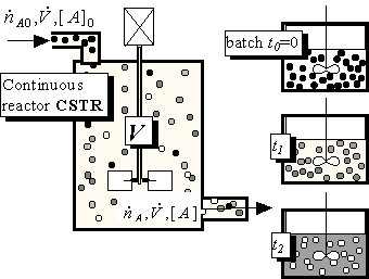
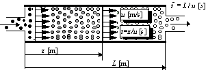
Remark: Maybe the figure is slightly misleading, because the particles drawn in Fig.8.14 are changing their colours continually; in the simple world of inorganic chemistry this is not usually so: a molecule of CO2 either exists or does not, particles should be either white or black, nothing in between. Only in this case it is possible to match the distribution of particles inside the CSTR with the distribution in the batch reactor at a particular time t and only then (at time t) will the rate of chemical reaction be the same in the batch and in the continuous reactor. The gradually changing state (colour) of particles is typical for bio-substances, composed of continually growing or decaying macromolecules; this is an unpleasant complication, because it is not possible to find an exact match between the distributions of reactants and products in a CSTR and a batch reactor. Therefore the data from a batch experiment or from rate equations like (8.24) should not be used for calculating continuous systems (at least theoretically). Fortunately, the situation is not as bad as it seems, and even the changes of bio-substances can be described in a classical way.
As an example of a calculation in a CSTR at steady state we shall suppose that only species A reacts, and that the reaction is of the r-th order. We shall write equations for the concentrations of species A in a batch reactor and in a CSTR:
(8.62,63)

where V is the volume of the CSTR and is the volumetric flowrate [m3.s-1]. Equation (8.62) has been solved (see (8.29)) and Eq. (8.63) is only algebraic and not a differential equation for a concentration in the CSTR. For the first order reaction (r=1) the solutions are given by
(8.64,65)

Which reactor is better? If we select as a criterion of optimal design the maximum performance for a given reactor size (internal volume V), it is sufficient to compare (8.64) and (8.65) at a mean residence time , because at this time the volume of substance processed in the CSTR is V, the volume of the reactor. Relative decreases of concentrations [A]/[A]0 are:

So, which is less? You have two ways to get an answer: work or think; work involves using a calculator or a spreadsheet, think involves using your brain, e.g.: exp(kt)=1+kt+(kt)2/ 2+... (Taylor expansion) > 1+kt . Or simply: for kt->inf and kt=0 both expressions are equal, and for kt=1 it holds that e>2. Therefore the left side ( exp(-kt) ) is smaller than the right hand side (1/(1+kt) ) at any time t, and the concentration of species A is lower (and the yield higher) in the batch reactor. This is an important conclusion:
A CSTR, a continuous system with ideal mixing, has a worse performance than the plug flow continuous system or a batch reactor.
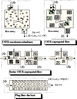
It can be shown that this conclusion is also valid for chemical reactions of an order higher than one. A real reactor is always something between these limiting cases, and a very useful model for describing a nonideal continuous reactor consists of a series of CSTR. A comparison of- a single CSTR,
- a series of CSTR, and
- a plug flow reactor
|
Note that there are two modifications of ideally mixed reactor CSTR,
micromixing and macromixing
: the first (and the worst from the point of view of yield if the reaction order is higher than one) is characterised by a random distribution of molecules, and the second by random distribution of tiny "batch microreactors" inside the CSTR. Both variants have practically the same residence time distribution, but in the first case the conversion is calculated according to (8.65), while the segregated flow is calculated according to eq. (8.61). The same procedure can be used for a series of CSTR (segregated and maximum mixedness regimes should be distinguished again), the only difference being the residence time distribution. I hope that Fig.8.16 clearly demonstrates that, in the plug flow region, the difference between segregated and maximum mixedness regimes disappears.Remark: Residence time distribution E(t) for a single CSTR is an exponential function (see e.g., Levenspiel (1956)), the time course of concentration of A in a batch reactor for r=1 is also an exponential function, see Eq. (8.64) and thus integral (8.61) can be integrated analytically
(8.66)

This is exactly the same result, obtained under the assumption of maximum mixedness, Eq.(8.65). This only supports the previous conclusion that the first order reactions (usually monomolecular reactions) give the same yield regardless of the segregated flow or maximum mixedness regime. Therefore it does not matter which method we select for evaluating CSTR series, assuming a first order reaction (micromixing is easier). As the volume of each CSTR is V/N (N-is number of vessels, V is reactor volume) the material balance of [A] species is (see 8.63)
(8.67)

and the concentration at the outlet of the last vessel [A]N can be expressed in terms of the concentration in the preceding vessel [A]N-1 according to Eq. (8.67) and using the definition of the mean residence time . Repeating this substitution recursively, the following relation between inlet and outlet concentration is obtained
(8.68)

If we increase N to infinity (dividing the actual reactor into an infinite number of infinitesimally small CSTRs, and preserving volume V) we obtain
(8.69)

and this is the conversion (8.64) of the plug flow reactor!
CSTR and plug flow reactors are basic elements of a kit for the construction of complex models. These models are suitable for flow descriptions in real reactors, and a series of CSTRs is such an example. Other examples are parallel series of CSTRs (e.g., a description of the parallel multiphase flows), models of short cut flows by plug flow units, dead zones or zones with poor interchange of mass with the mainstream, etc.
The computational procedure of a reactor described by these models remains, the only difference being in the more involved calculations of the residence time distribution E(t), which is needed in Eq. (8.61). An important class of combined models are models of recirculation. The simplest arrangement is in Fig.8.17.
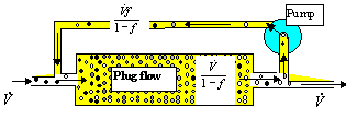
The recirculation ratio f Î(0,1) is the ratio of flowrate in the recycle loop with respect to the flowrate through the apparatus. The interesting thing is: when increasing the recirculation ratio up to 1, the system tends to behave like a CSTR, like an ideally mixed vessel, regardless of the basic unit used (plug flow in Fig.8.17). This means that recirculation always worsens the performance (yield) of a system (there is nothing so bad as a CSTR). This conclusion is rather general:
recirculation has in principle an adverse effect on most continuous processes
(and not only on chemical reactors - on evaporators, dryers, heat exchangers and sterilisers, too). The residence time distribution is very widespread, which means that the substance is processed nonuniformly.
Recirculation could be introduced in an university, too: e.g., 90% (f=0.9) of randomly selected students will be returned after graduation to the first semester. Then you will be sitting in a classroom with tired colleagues of forty, fifty, or sixty years of age, with beginners and with others who are repeating this course for the tenth time (these differences of age are characterised by the residence time distribution, E(40) is simply the number of your 40 year old classmates). What a ridiculous picture! Of course, there will also be a positive effect: The number of students will be increased, and also the university's income. Teaching staff will be instantaneously trained. There are always good specific reasons for recirculation: increasing f increases the flowrate through apparatuses, and thus some processes can be intensified - e.g. heat and mass transfer, cleaning of internal surfaces, etc. Recirculation of flue gases decreases the temperature of combustion, thus reducing the production of NOx. Recirculation of drying air in dryers saves energy and is required in cases when the dried material does not like dry air. Etc., etc. Be that as it may, have in mind that the necessity of recirculation indicates that there is something wrong in the basic system, and what is wrong can be improved (except bad character). Sometimes the outlet stream is separated, e.g., according to its composition and only the part which requires further processing is recirculated (this is something quite different, and selective recirculation eliminates most negative effects). This technique is used, for example, in some bio-reactors, where enzymes (catalysts) are separated by ultrafiltration and returned to the inlet of the reactor to promote bio-reaction - cultivation of biomass.

 ). Then the yield of the continuous
reactor is calculated as the sum of the yields of the batch microreactors having
capacity
 are the ratios of mass flowrates of streams with residence time ti over the total
flowrate. If we select the times t1 , t2, ...,t i, ti+1,... equidistantly (i.e., t
i+1 -ti =Dt constant), the
ratio has dimension 1/s and is called the Residence Time Distribution. Using this we can
substitute the sum in Eq.(8.60) by the integral for Dt->0
