|
|
Department of process engineering U218Flow inversion |
|
The slowly flowing fluid near the wall should be transferred to the central region of pipe and vice versa. Suggested general model of flow inversion has only one parameter (flowrate ratio in the intermediate stream 2 with respect to total flowrate /Fig/). |
This model enables to describe residence time distribution and
temperature distribution behind the invertor in an analytical form.
Thus the axial course of heat transfer coefficient and relative heat
transfer enhancement may be evaluated.
The heat transfer is increased because the flow invertor transports yet unheated
portion of material towards the hot wall:
 Relative increase of Nusselt number predicted by this model is shown on the graph Nu-1/Gz (Gz denotes Graetz number). |
|
Partial flow inversion occurs e.g. in static mixers, and very
efficient designs make use of centrifugal forces in spirals, coiled tubes etc.
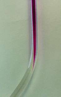
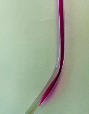
The following theoretical, numerical and experimental analysis concentrates upon local bending of tube: we try to find out such a geometry, which produces just 1/2 rotation of fluid in cross-section of pipe. |
Theoretical analysis predicts, that for optimal inversion
the relation should hold. Phi is the incline (in radians) of the straight sections of the pipe; the higher is flowrate, the smaller should be the angle (for Re=1000 is the optimal incline approximately 18 deg). As a measure of inversion efficiency the time of the first appearance of tracer can be used. In a straight empty tube this first appearance time is one half of mean residence time (t=0.5). Theoretical analysis predicts maximum t=0.61 (the higher is this value, the better is residence time distribution) and experiments show that the actual efficiency is even higher (t=0.66). This dicrepancy may be atributed to the fact, that the theoretical analysis neglects the internal volume of invertor (bend) with respect to the volumes of straight sections. |
 |
Stimulus-response technique using KCl solution as
a tracer (injection from three needles with 7 calibrated holes
/the amount of injected tracer should be proportional to mass
flowrate in given portion of cross-section).
The pulse is detected by 4 conductivity probes (paralel platinum wires) and conductometers. Both the stimulus and response are evaluated from pairs of probes with different characteristics (lengths of wires), so that the mean mass concentration of tracer can be evaluated. The flowrate is measured by weighting. Measured responses are evaluated by computer program (corrections, normalization, identification of impulse response). |