Department of process engineering U218Continuous direct ohmic heating |
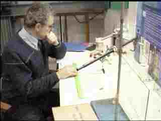
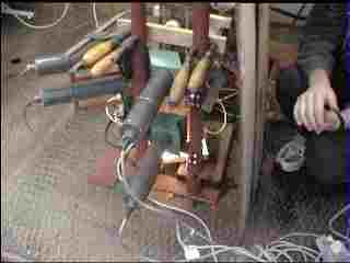
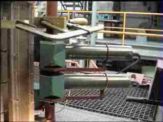
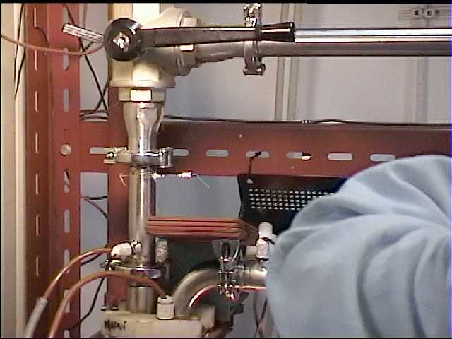
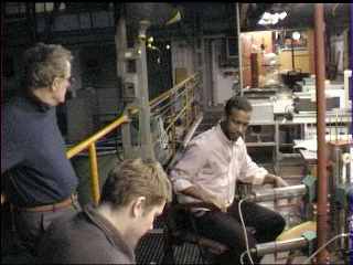
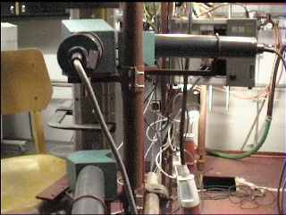
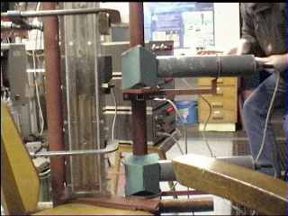
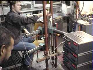
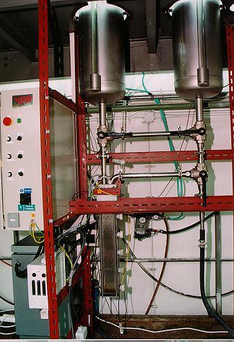 Experimental rig (CTU-FME-Process engineering) |
 |
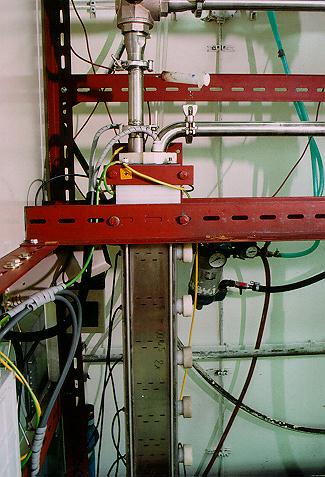
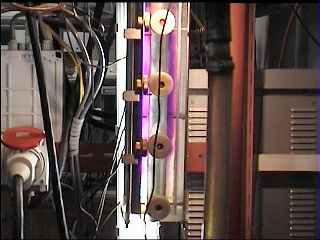
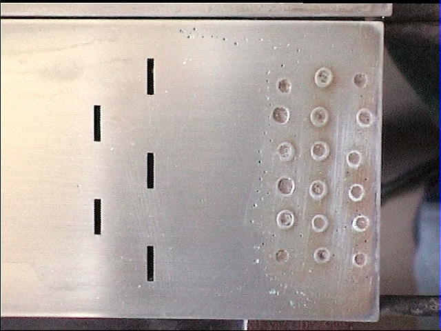
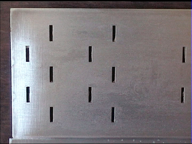
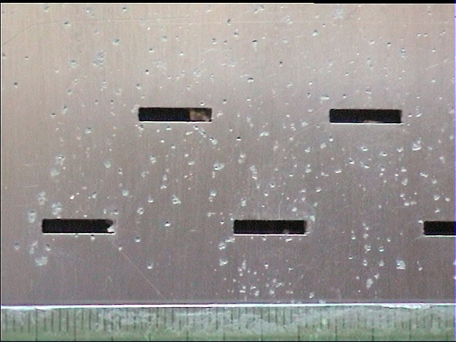
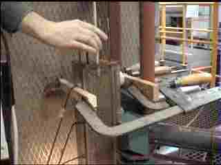
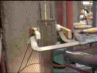
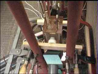
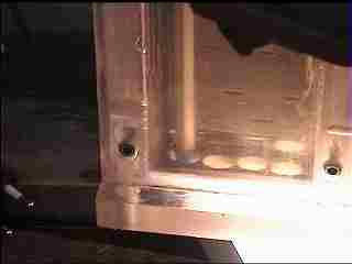
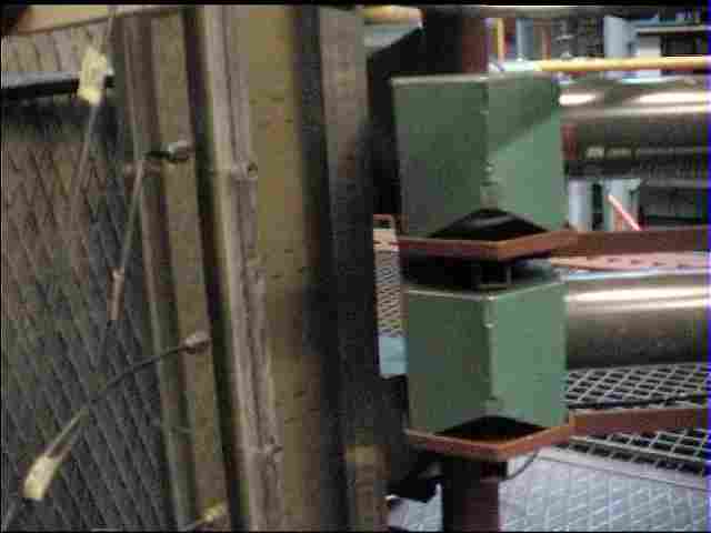
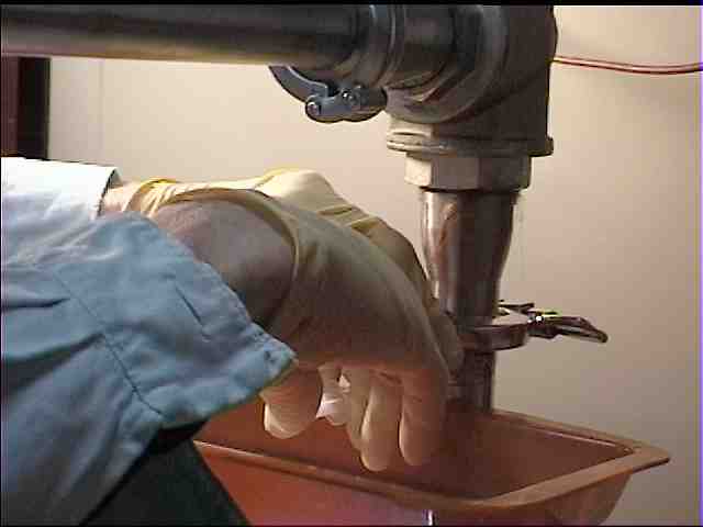
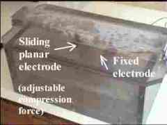
Heater section (inlet and outlet from above)

|
Direct ohmic heating PRO/CONSDirect ohmic heating can operate in:
CONTINUOUS DIRECT OHMIC HEATING OF LIQUIDS, Int. CHISA 98, describing theoretical modelling of RTD, velocity and temperature field, as well as experimental results. You can also try the Excell sheet ohm-pde.zip [250 KB!] ohm-pde.xls [840 KB!] solving 2D voltage distribution in the continuous heater, temperature and velocity field, for temperature dependent electrical conductivity, viscosity and density. Partial differential equations are solved by using finite differences (biharmonic equation for stream function converges only for Re<150). |
|
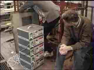
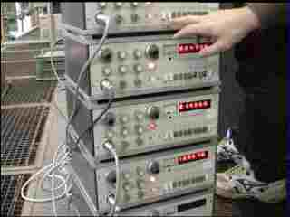
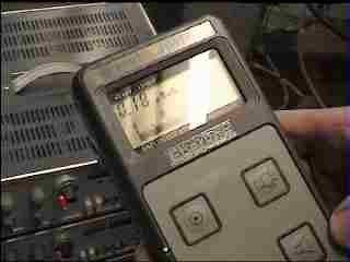
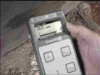
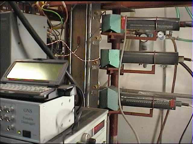
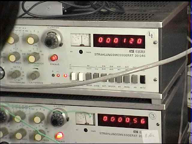
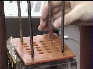
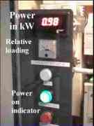
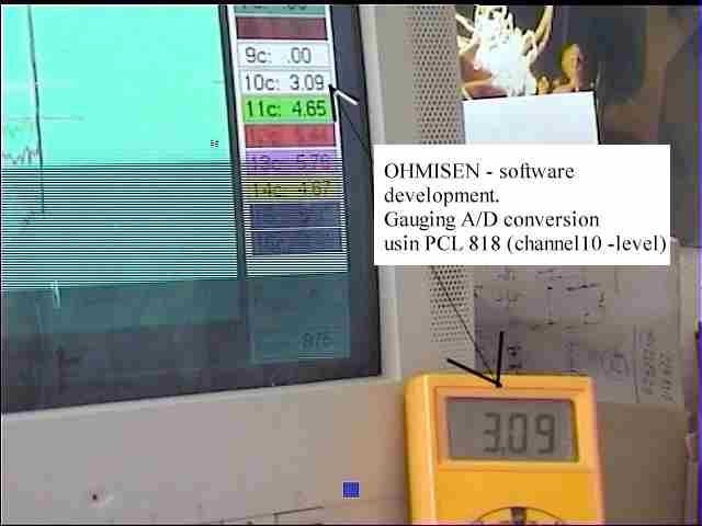
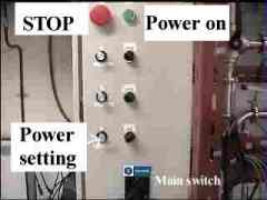
Control and measuring equipmentWhat is measured:
All outputs from transdures (0-10 V) are sampled and evaluated by a PC using A/D card Advantech PCL 818. Programs OHMICAD/OHMICAS were developed for monitoring temperatures, flowrate and electrical power (testing).
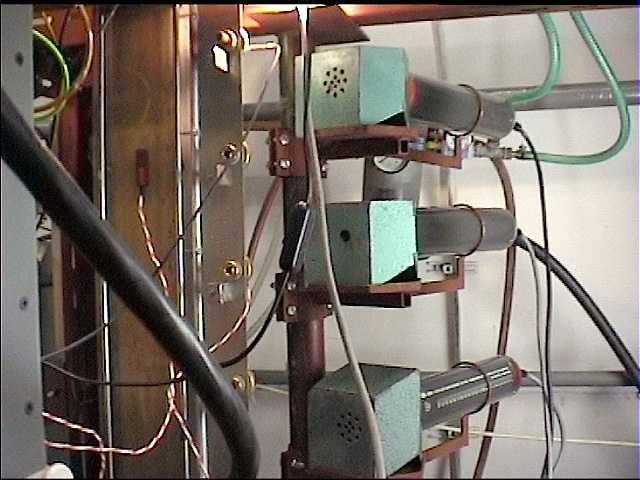
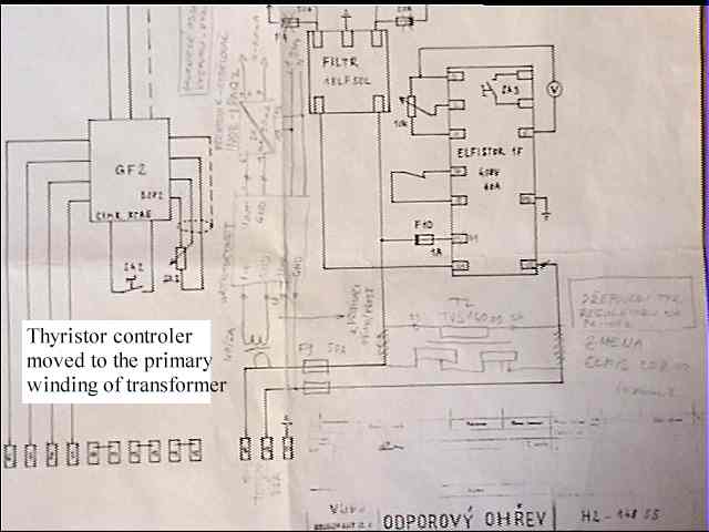
Power source
(Circuit diagram)
|
 |
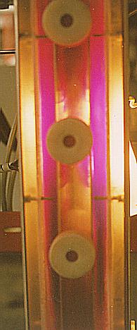
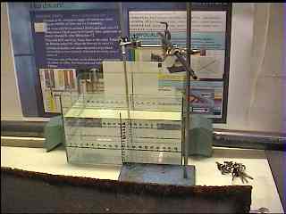
Flow visualisation by instantaneous injection of potassium permanganate solution |
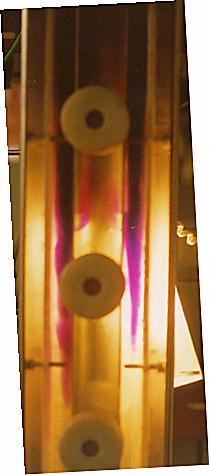
Volumetric flowrate 48 ml/s. 22 seconds after injection of tracer. |
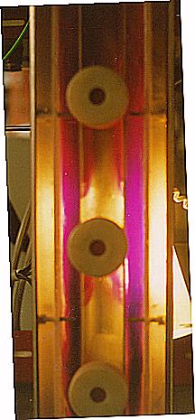
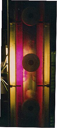
Volumetric flowrate 48 ml/s. 29 seconds after injection of tracer. |
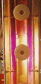
Volumetric flowrate 76 ml/s. 10 seconds after injection of tracer. |
Volumetric flowrate 76 ml/s. 14 seconds after injection of tracer. |
Volumetric flowrate 140 ml/s. 16 seconds after injection of tracer. |
Full Electrodes (RTD measurement) Inserted 21.7.2000 | ||||
|---|---|---|---|---|
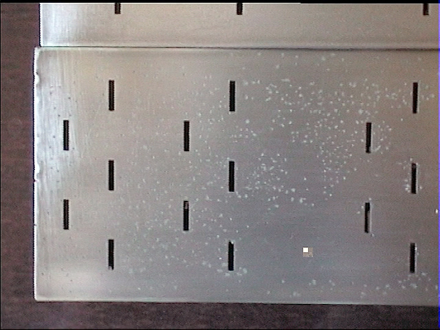
Volumetric flowrate 33 ml/s. Video [0.7MB], top. |
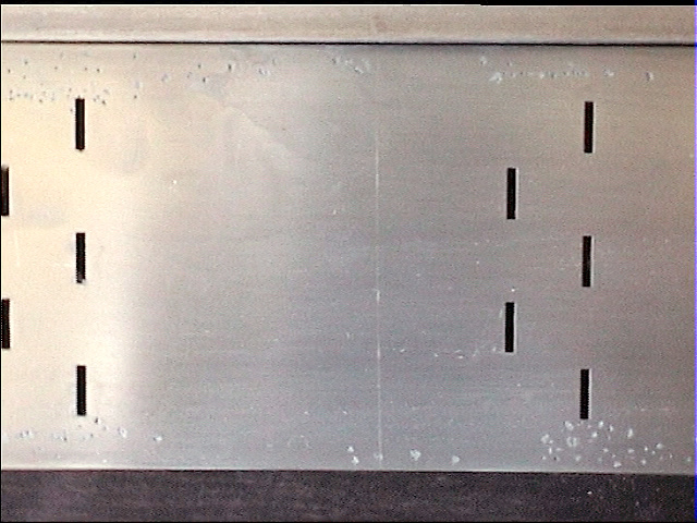
Volumetric flowrate 75 ml/s. Video [0.7MB], bottom. |
Volumetric flowrate 33 ml/s. Video [0.8MB], position 2-3. |
Volumetric flowrate 72 ml/s. Video [0.8MB], position 2-3 from top. |
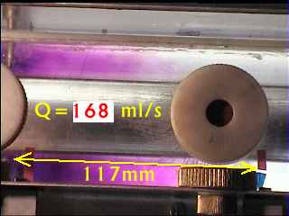
Volumetric flowrate 168 ml/s. Video [0.8MB], position 2-3 from top. |
Full Electrodes (HEATING and RTD measurement) Inserted 24.7.2000 | |
|---|---|
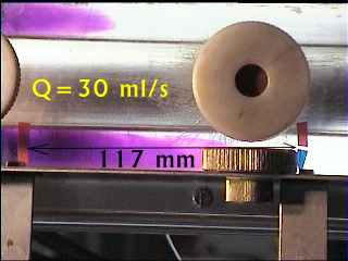
Volumetric flowrate 30 ml/s. Video [0.7MB], Influence of buoyancy: Flow in one lateral channel is suppressed. |
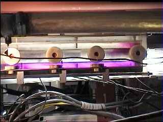
Volumetric flowrate 33 ml/s. Video [0.7MB], overall frontal view. |
Asymmetry of flow in lateral channels VIDEO [0.7MB]Inserted 4.10.2000 | |||
|---|---|---|---|
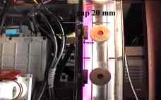 P=0 kW, h=18 mm, V=41 ml/s.
Flow preserves symmetry in both channels. |
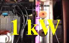 P=1 kW, h=18 mm, V=41 ml/s.
Right channel suppressed. |
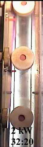
 P=2 kW, h=18 mm, V=41 ml/s.
Right channel suppressed. |
|
Flow resistance increased by decreasing width of lateral channels | |||
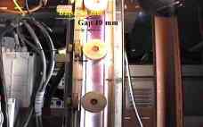 P=0 kW, h=11 mm, V=41 ml/s.
Flow preserves symmetry. |
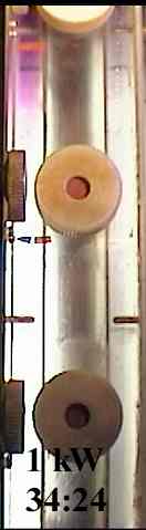
 P=1 kW, h=11 mm, V=41 ml/s.
Symmetry preserved. |
 P=2 kW, h=11 mm, V=41 ml/s.
Right channel is slightly suppressed. |
|
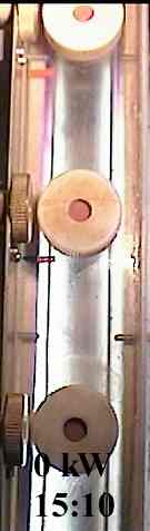
 P=0.5 kW, h=11 mm, V=41 ml/s.
Flow preserves symmetry. |
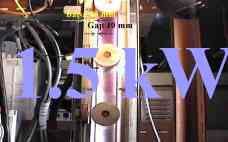 P=1.5 kW, h=11 mm, V=41 ml/s.
Symmetry preserved. |
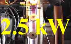 P=2.5 kW, h=18 mm, V=41 ml/s.
Right channel suppressed. |
|
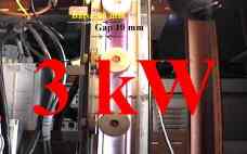 P=3 kW, h=11 mm, V=41 ml/s.
Right channel supressed. |


 Time sequences (photographs)
|
||
| Central injection P=0 kW, Q=67.4 ml/s, KMnO4 | Central injection blue ink | Central injection china ink |
| Lateral injection KMnO4, Q=67.4 ml/s | Lateral injection (upwind) | Q=0 - influence of density |
 Simple model [Word 7] analysing situation when the flow in the right channel is stopped by buoyancy.
Numerical simulation is available as source program CVASYM.FOR or executable form. More details are in paper Zitny Thyn: Parallel flow asymmetries... Nancy 2001 [Word7 300KB] Inserted 31.3.2001 or in manuscript Zitny R.: Stability of flow in parallel channels [Word7] Modified 25.5.2001 Properties of water[Excel 35K] for evaluation of data.Inserted 21.5.2001 Experimental data Z G (Excel) Inserted 22.6.2001 Processing of camera records in VELOVIDE.XLS Inserted 9.8.2001 |
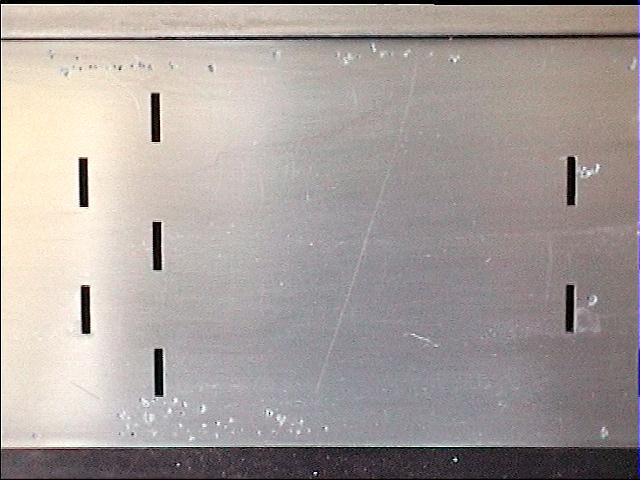
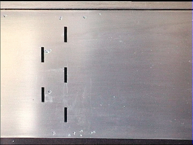
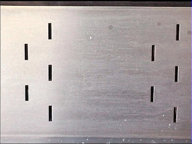
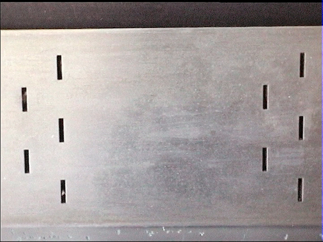
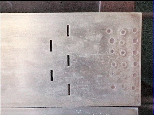
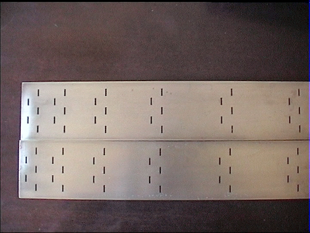
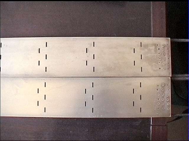
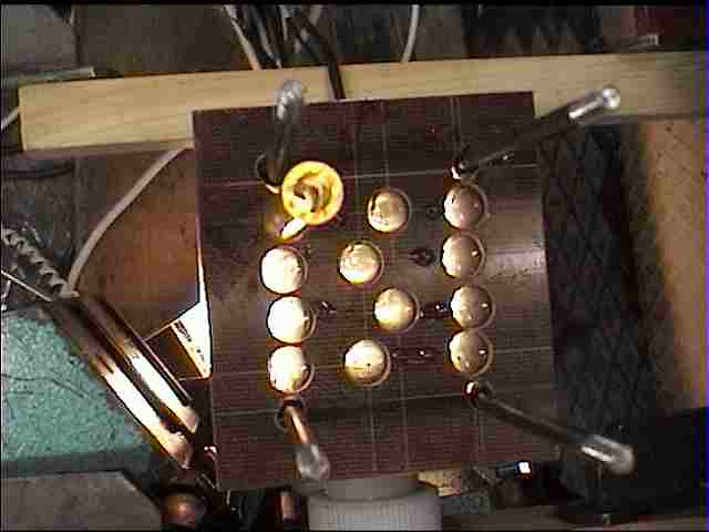
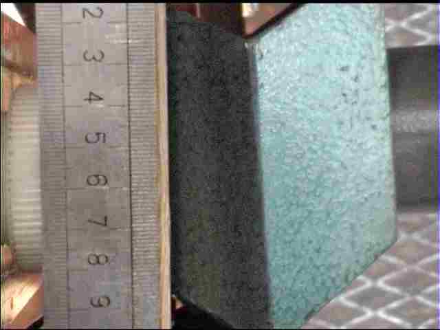
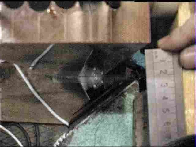
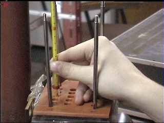
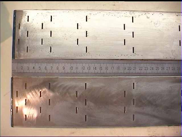
Electrodes before assembly Inserted 24.8.1999 | ||||
|---|---|---|---|---|
|
|
|
|
|
|
|
|
|
|
|
|
|
||
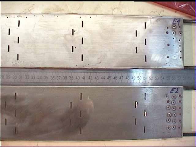
| Electrodes before assembly Inserted 19.3.2001 | ||||
| Bottom | Top | |||
Collimated detectors - point source (Cs, 3.6 mC) Inserted 8.12.1999Measured by Thyn, Spevacek, Kares | ||||
|---|---|---|---|---|
|
|
|
|
|
|
|
|
|
|
|
|
|
|
|
|
|
|
|
|
Collimated detectors - Tc99 Inserted 20.10.2000Measured by Thyn, Blaha, Novy, Houdek, ZitnyNarrow lateral channels, full/perforated electrodes, power 0 - 5.5 kW, simultaneous measurement of conductivities and temperatures (MIC2000-Pt100 at lateral channels for flow asymmetry detection) | ||
|---|---|---|
|
|
|
|
|
|
Collimated detectors - Tc99 - Point source Inserted 5.12.2001Measured by Thyn, Chorche, Novy, HoudekLateral channels 18mm, full electrodes | ||
|---|---|---|
 |
 |
 |
 |
 |
 |
Batch ohmic heating-properties at 50Hz | ||
|---|---|---|
 |
 |
 |
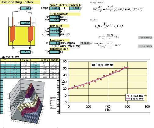 Excell spreadsheet for modelling the heater.
|
||
Supposed development(only design and mathematical modelling has been done) | |
|---|---|
| Design 1 | Description |
|
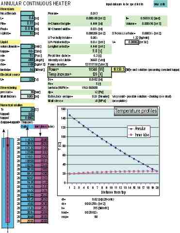
Design assumes helical flow of heated liquid in an annular space
between two tubular electrodes (Fig. shows only one-threaded helix for clarity, however actual design would be
double threaded helix).
Flow arrangement is similar to the current heater, replacing planar electrodes by tubes and reverting direction of flow
(preheating takes place in the central channel).
 Excell spreadsheet for modelling the heater.
Possible advantages:
Excell spreadsheet for modelling the heater.
Possible advantages:
|
| Design 2 | Description |
|
Flexible helix ends with a ring, sealing the annular gap. This ring pulls ribbons of helix even
at a small flowrate.
|